Pneumatic connectors
Pneumatic connectors with Simultaneous connection :
Modular rectangular electropneumatic connector
Made in anodised aluminium alloy, it ensures the simultaneous connection of 12
Pneumatic circuits of diameters 4, 6 or 8mm and electric signals (see table).
Selective disconnection under pressure is authorised according to choice of inserts.
Connector components :
Housing
| Housing | ||
| Connector version A | ||
| Pneumatic part | Electric part | Protection |
| 5 ways Dia. 4, 6, 8 mm Male,female,auto shut-off Part N° CRX12 PG29 / 5PP Part N° CRX12 PG42 / 5PP | 1 module 5, 10, 20 contacts male ou female inserts | Housing Part N° M9500055 |
| Connector version B | ||
| 4 passages 4 ways Dia. 4, 6, 8 mm Male,female,auto shut-off Part N° CRX12 PG29 / 4PP Part N° CRX12 PG42 / 4PP | 1 module 5, 10, 20 contacts male ou female inserts | Housing Part N° M9500055 |
| Connector version C | ||
| 2 ways Dia. 4, 6, 8 mm Male,female,auto shut-off Part N° CRX12 PG29 / 2PP Part N° CRX12 PG42 / 2PP | 1 to 4 modules 5, 10, 20 contacts male ou female inserts | Housing Part N° M9500055 |
Base
| Base | ||
| Connector version A | ||
| Pneumatic part | Electric part | Protection |
| 5 ways Dia. 4, 6, 8 mm Male,female,auto shut-off Part n° ERX12 / 5PP | 1 module 5, 10, 20 contacts insert mâle ou femelle | Housing Part N° M9500052 |
| Connector version B | ||
| 4 ways Dia. 4, 6, 8 mm Male,female,auto shut-off Part n° ERX12 / 4PP | 1 module 5, 10, 20 contacts insert mâle ou femelle | Housing Part N° M9500052 |
| Connector version C | ||
| 2 ways Dia. 4, 6, 8 mm Male,female,auto shut-off | 1 to 4 modules 5, 10, 20 contacts male ou female inserts | Housing Part N° M9500052 |
Choice of different connector components :
Pneumatic part
| Pneumatic part | ||
| Description | Part n° | Code |
| Pneumatic and electric bases and supports | ERX 12 / 5 PP | P 464 |
| ERX 12 / 4 PP | P 463 | |
| ERX 12 / 2 PP | P 462 | |
| Pneumatic and electric housing PG29 and supports | CRX 12 PG 29 /5 PP | P 467 |
| CRX 12 PG 29 / 4 PP | P 466 | |
| CRX 12 PG 29 / 2 PP | P 465 | |
| Pneumatic and electric housing PG42 and supports | CRX 12 PG 42 / 5 PP | P 470 |
| CRX 12 PG 42 / 4 PP | P 469 | |
| CRX 12 PG 42 / 2 PP | P 478 | |
Insert
| Insert | |||
| Description | Dia.(mm) | Part n° | Code |
| Male insert | 4 | IM 4 | P 453 |
| 8 | IM 8 | P455 | |
| Female insert | 4 | IF 4 | P 456 |
| 6 | IF 6 | P 457 | |
| 8 | IF 8 | P 458 | |
| Auto shut-off insert | 4 | IFA 4 | P 459 |
| 6 | IFA 6 | P 460 | |
| 8 | IFA 8 | P 461 | |
Protection cover
| Protection cover | ||
| Description | Part n° | Code |
| Base cover | CPE 12 | M 950052 |
| Housing cover | CPE 12 | M 950055 |
Electrical part
| Electrical part | |||||||
| Modules | Crimped contacts | ||||||
| Inserts | Part N° | Code | Dia. (mm) | Type | Connection dia (mm2) | Part n° | Code |
| Contacts 5 male 400V / 50A | M5M | P471 | 2,5 | mâle tourné | 0,75 -1 | CMT 2,5 -1 | P477 |
| 1,5 | CMT 2,5 -1,5 | P478 | |||||
| 2,5 | CMT 2,5 -2,5 | P479 | |||||
| Contacts 5 female 400V / 50A | M5F | P472 | 2,5 | femelle tournée | 0,75 -1 | CFT 2,5 -1 | P480 |
| 1,5 | CFT 2,5 -1,5 | P481 | |||||
| 2,5 | CFT 2,5 -2,5 | P482 | |||||
| Contacts 10 male 250V / 10A | M10M | P473 | 1,6 | mâle tourné | 0,5 | CMT 1,6 -0,5 | P483 |
| 0,75 | CMT 1,6 -1 | P484 | |||||
| 1,5 | CMT 1,6 -1,5 | P485 | |||||
| Contacts 10 female 250V / 10A | M10F | P474 | 1,6 | femelle tournée | 0,5 | CFT 1,6 -0,5 | P486 |
| 0,75 | CFT 1,6 -1 | P487 | |||||
| 1 | CFT 1,6 -1,5 | P488 | |||||
| Contacts 20 male 63V / 5A | M20M | P475 | 1 | mâle estampé | 0,80 -0,2 | CME 1 -0,2 | P489 |
| 0,2 -0,52 | CME 1 -0,5 | P490 | |||||
| Contacts 20 female 63V / 5A | M20F | P476 | 1 | femelle estampée | 0,80 -0,2 | CFE 1 -0,2 | P491 |
| 0,2 -0,52 | CFE 1 -0,5 | P492 | |||||
Pneumatic connectors with Simultaneous connection :
Bulkhead connector
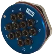 | 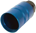 |  |
| Bulkhead connector | Long housing | Mounting bracket |
Made in blue anodised aluminium alloy, it ensures simultaneous connection of from 4 to 21 circuits of diameter 4, 6, 8 or 10mm and can be used on multiple bulkheads.
This connector is available in diameters 50 and 80mm and offers the advantage of being able to choose the tool-less components. The connection is polarised and the long housings ensure mechanical support to the multitubes.
Working pressure is 12 bars and disconnection under pressure is not authorised.
Choice of bulkhead connector
Choice of bulkhead connector
| N° of tube | Dia. tube | Dia. connector | Dia. multitube | Cable gland size | Cable gland capacity | Panel thickness |
| 7 | 4 | 50 | 15,5 | PG 29 | 25 to 15 mm | 1 to 8 mm |
| 12 | 4 | 50 | 20,5 | PG 29 | 25 to 15 mm | 1 to 8 mm |
| 21 | 4 | 80 | 23,5 | PG 29 | 25 to 15 mm | 1 to 8 mm |
| 7 | 6 | 50 | 21,5 | PG 29 | 25 to 15 mm | 1 to 12 mm |
| 12 | 6 | 80 | 28,5 | PG 42 | 38 to 25 mm | 1 to 12 mm |
| 4 | 8 | 50 | 23 | PG 29 | 25 to 15 mm | 1 to 12 mm |
| 7 | 8 | 80 | 27,5 | PG 42 | 38 to 25 mm | 1 to 12 mm |
| 12 | 8 | 80 | 36,5 | PG 42 | 38 to 25 mm | 1 to 12 mm |
| 4 | 10 | 80 | 27,5 | PG 42 | 38 to 25 mm | 1 to 15 mm |
| 7 | 10 | 80 | 33,5 | PG 42 | 38 to 25 mm | 1 to 15 mm |
Part n°
Part n°
| N° of tube | Part n° | ||
| Mounting bracket | Bulkhead connector PC | Long housing CPLT | |
| 7 | P 205 | P 230 | P 202 |
| 12 | P 205 | P 231 | P 202 |
| 21 | P 206 | P 232 | P 203 |
| 7 | P 205 | P 233 | P 202 |
| 12 | P 206 | P 234 | P 203 |
| 4 | P 205 | P 235 | P 202 |
| 7 | P 206 | P 236 | P 203 |
| 12 | P 206 | P 237 | P 203 |
| 4 | P 206 | P 238 | P 203 |
| 7 | P 206 | P 239 | P 203 |
Diagram
Diagram

Assembly
Assembly
 | ||||||
Mounting bracket | Long housing | Cable gland | Mounting bracket | |||
Pneumatic connectors with Simultaneous connection :
Tool-less push-in round connector
 | 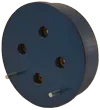 | 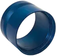 |  |  |
| panel base | housing base | short housing | long housing | mounting bracket |
Made in blue anodised aluminium alloy, it ensures simultaneous connection of from 2 to 21 circuits of diameters 4, 6, 8 or 10mm.
This connector has the added advantage of allowing the choice of the different components without any tools.
Connection is polarised and the long housings afford mechanical support to the multitubes.
Working pressure is 12 bars and disconnection under pressure is not authorised.
Choice of connector
Choice of connector
| N° of tube | Dia. tube | Dia. connector | Dia. du multitube | cable gland size | cable gland capacity | panel thickness |
| 7 | 4 | 50 | 15,5 | PG 29 | 25 to 15 mm | 1 to 4 mm |
| 12 | 4 | 50 | 20,5 | PG 29 | 25 to 15 mm | 1 to 4 mm |
| 21 | 4 | 80 | 23,5 | PG 29 | 25 to 15 mm | 1 to 6 mm |
| 7 | 6 | 50 | 21,5 | PG 29 | 25 to 15 mm | 1 to 4 mm |
| 12 | 6 | 80 | 28,5 | PG 42 | 38 to 25 mm | 1 to 4 mm |
| 2 | 8 | 50 | 19,5 | PG 29 | 25 to 15 mm | 1 to 6 mm |
| 4 | 8 | 50 | 23 | PG 29 | 25 to 15 mm | 1 to 4 mm |
| 7 | 8 | 80 | 27,5 | PG 42 | 38 to 25 mm | 1 to 6 mm |
| 12 | 8 | 80 | 36,5 | PG 42 | 38 to 25 mm | 1 to 6 mm |
| 2 | 10 | 50 | 23,5 | PG 29 | 25 to 15 mm | 1 to 6 mm |
| 4 | 10 | 80 | 27,5 | PG 42 | 38 to 25 mm | 1 to 6 mm |
| 7 | 10 | 80 | 33,5 | PG 42 | 38 to 25 mm | 1 to 6 mm |
Part n°
Part n°
| N° of tube | Part n° | ||||
| Mounting bracket | Panel base EAR | Housing base ECA | Short housing CPC | Long housing CPLT | |
| 7 | P 205 | P 004 | P 104 | P 200 | P 202 |
| 12 | P 205 | P 005 | P 105 | P 200 | P 202 |
| 21 | P 206 | P 018 | P 118 | P 201 | P 203 |
| 7 | P 205 | P 009 | P 109 | P 200 | P 202 |
| 12 | P 206 | P 010 | P 110 | P 201 | P 203 |
| 2 | P 205 | P 011 | P 111 | P 200 | P 202 |
| 4 | P 205 | P 012 | P 112 | P 200 | P 202 |
| 7 | P 206 | P 013 | P 113 | P 201 | P 203 |
| 12 | P 206 | P 014 | P 114 | P 201 | P 203 |
| 2 | P 205 | P 015 | P 115 | P 200 | P 202 |
| 4 | P 206 | P 016 | P 116 | P 201 | P 203 |
| 7 | P 206 | P 017 | P 117 | P 201 | P 203 |
Diagram
Diagram

Assembly
Assembly
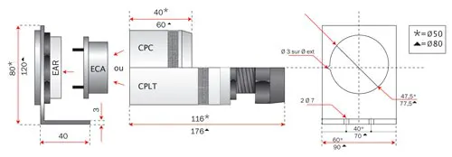 | ||||||
Mounting bracket | Housing base | Housing short or long | Cable gland | Mounting bracket | ||
Pneumatic connectors with Simultaneous connection :
Tool-less modular rectangular connector
 |  |  |  | |
| fixed base | housing | female insert | male insert | auto shut-off insert |
Made in anodised aluminium alloy and plated brass for the inserts, it allows connection of from 1 to 12 tubes (dias. 4, 6 or 8mm) full flow or with auto shut-off using normalised connectors.
This connector offers the advantage of the choic of components without tools.
Selective disconection under pressure is possible according to choice of female inserts.
It has a polarised assembly and its working pressure is 12 bars.
Inserts are pin-mounted.
Different sections can be mounted on the same circuit and are totally mixable for diameters 4, 6 and 8mm
Choice of connector
Choice of connector
| Rectangular pneumatic connectors (family PF418) | |
| Part N° | Description |
| P452 | Embase fixe ERX12 |
| P451 | Capot presse étoupe 29 CRX PG 29 |
| P450 | Capot presse étoupe 42 CRX PG 42 |
| M9500052 | Capot de protection pour embase CPE 12 |
| M9500055 | Capot de protection pour capot CPC 12 |
| P453 | Insert mâle IM Ø4 |
| P455 | Insert mâle IM Ø8 |
| P456 | Insert femelle IF Ø4 |
| P457 | Insert femelle IF Ø6 |
| P458 | Insert femelle IF Ø8 |
| P459 | Insert femelle auto-obturable IFA Ø4 |
| P460 | Insert femelle auto-obturable IFA Ø6 |
| P461 | Insert femelle auto-obturable IFA Ø8 |
Protection
Protection
| Impossibility to mount in housing | Cable gland clamping range | ||||
| Insert | Part n° | Tube Dia. 8 | Part n° | Dia. | |
| Male | IM | 1-2-11-12 | PG 29 | dia.15 from to dia.25 | |
| Femelle | IF | 1-2-11-12 | PG 42 | dia.25 from to dia.38 | |
| auto shut-off | IFA | 1-2-3-4-9-10-11-12 | |||
Dimensions
Dimensions
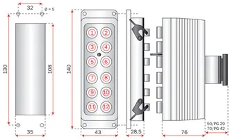 | ||||||||||
| cover plate | fixed base | housing and cable gland | ||||||||
Stackable spool valve module :
Stackable single spool valve module
 | 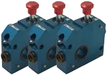 |  |  |
| Closure plate | Single spool module | Supply plate | Blanking plug |
Made in blue anodised aluminium alloy, it authorises pneumatic flow stoppage by a simple “push-pull” action with draining via a sintered brass silencer.
Its 1/2” bsp supply ensures full flow for a working pressure of 12 bars.
Its modularity allows mounting of as many valves as required with foolproof assembly and lockable function.
Choice of module
Choice of module
| Module | Supply plate | Closure plate | Accessories | Code |
| RBM 1T8 | P410 | |||
| RBM 1T 1/4 GAZ | P421 | |||
| RBM 1T 1/4 NPT | P425 | |||
| RBA 1T | P411 | |||
| RBF 1T | P412 | |||
| Lock Part N° C | P322 | |||
| Blanking plug Part N° RBO | P312 |
Diagram
Diagram
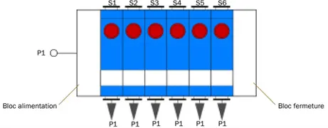
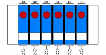
| A 3/2 “push-pull” valve |
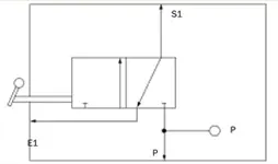 |
Series mounting with common pressure
Series mounting with common pressure
| S1 from to S6 = P1 |
 |
Parallel assembly without common pressure
Parallel assembly without common pressure
| S1 = P1 | S2 = P2 | S3 = P3 | S4 = P4 | S5 = P5 | S6 = P6 |
 | |||||
Stackable spool valve module :
Stackable twin spool valve module
 | 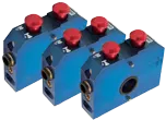 |  |  |
| Closure plate | Twin spool module | Supply plate | Blanking plug |
Made in blue anodised aluminium alloy, it authorises pneumatic flow stoppage via a simple “push-pull” action with draining through a sintered bronze silencer.
Its 1/2” bsp supply ensures full flow for a working pressure of 12 bars.
Its modularity allows the mounting of as many valsves as required with foolproof assembly and locking function.
This product is evolutive, offering the possibility of changing cartridge diameters (dia. 4, 6 or 8mm).
Choice of module
Choice of module
| Module | Supply plate | Closure plate | Accessories | Code |
| P403 | ||||
| P407 | ||||
| P406 | ||||
| P414 | ||||
| P424 | ||||
| P404 | ||||
| P405 | Lock Part N° C | P322 | ||
| Blanking plug Part N° RBO | P312 |
Evolutive cartridges : Part N° : FTL 8-4 / Part N° : FTL 8-6 / Part N° : FTLl 8
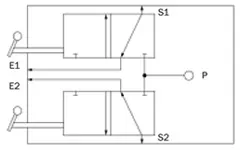
Diagram
Diagram
| Two 3/2 “push-pull” valves |
 |
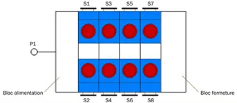
Series mounting with common pressure
Series mounting with common pressure
| S1 to S8 = P1 |
 |
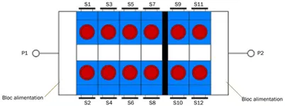
Series mounting with 2 common pressures
Series mounting with 2 common pressures
| S1 to S8 = P1 | S9 to S12 = P2 |
 | |
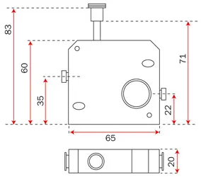
Dimensions
Dimensions
 |
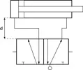
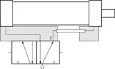
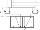
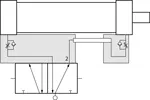
ISO 1 stackable base plates & cylinder base : |
Made in black anodised aluminium alloy, it ensures the mounting of the valve directly on the cylinder.
It can be coupled with the following functions :
- Speed control by flow reduction.
- Position locking by valve.
- Position detection by pressure drop valve.
The following table gives the different characteristics of monofuction and multifunction cylinder bases.
Characteristics of bases
Characteristics of bases
| cylinder bases | ||
| Monofunction | Multifunction | |
| Black anodised aluminium alloy | X | X |
| Pressure 12 bars | X | X |
| Cylinder mounting by ordinary banjo | X | X |
| Cylinder mounting by flow reducing banjo | X | X |
| Collected exhausts 1/4” or 3/8” bsp | X | |
| Independent exhausts 3/8” bsp (optional) | X | |
| Independent exhausts with integrated silencer | X | |
| Pilots - 12 - 14 in 3/8” bsp | X | |
| Supply port .1. by dia 8mm quick-connect | X | |
| Supply port .1 by 3/8” bsp | X | |
| Outlet - 2 - (see table of base choice) | X | X |
Choice of base
Choice of base
| Monofunction base | Part N° | Code |
| Outlet 2 : joint | EV1 SJ | P360 |
| Outlet 2 : 1/4” bsp | EV1 S 1/4”G | P361 |
| Multifunction base | Part N° | Code |
| Outlet 2 : joint | EV1 MJ | P362 |
| Outlet 2 : 1/4” bsp | EV1 M 1/4”G | P363 |
Assembly
Assembly
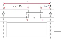
Working conditions : x>a+b
Tube cut : T = x-136
Diagram
Diagram
| standard | with cylinder base |
 |  |
 |  |
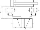 | 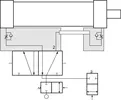 |
| D = X meter | D = 0 |
For parallel mounted cylinders : please consult us
ISO 1 stackable base plates & cylinder base :
ISO 1 stackable base plates with interruptible nominal pressure
 | 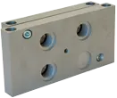 | 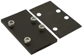 |  |
| ISO T1 bases | Blanking plate | End plates | Plugs |
Made in black anodised aluminium alloy, it ensures actuator drain whilst maintaining stackability.
Exhaust is collected at 12 bars maximum with lubricated or dry air. locking is an optional availability.
This product is evolutive as it offers the possibility of changing cartidge diameters (4, 6 or 8mm).
Choice of a base
Choice of a base
| INF | Réf | LAT | Réf | DS | Réf | ||
| ET1 INF 1 | P 300 | ET1 LAT 1 | P 301 | ET1 DS 1 | P 315 | ||
| ET1 INF 2 | P 311 | ET1 LAT 2 | P 314 | ET1 DS 2 | P 316 | ||
| ET1 INF 3 | P 319 | ET1 LAT 3 | P 320 | ET1 DS 3 | P 321 | ||
| ET1 INF 4 | P 322 | ET1 LAT 4 | P 324 | ET1 DS 4 | P 326 | ||
| ET1 INF 5 | P 323 | ET1 LAT 5 | P 325 | ET1 DS 5 | P 327 |
Locking option : Part N° C / code : P322
Evolutive cartridges : Part N° FTL 8-4 / Part N° FTL 8-6 / Part N° FTL 8
Example
Example

Diagram
Diagram
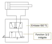
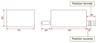
Dimensions
Dimensions


 Department specialized in manufacturing high-quality industrial hoses for fluid transfer.
 Specialist in the manufacturing of hydraulic hoses, extrusion of pneumatic tubes, and production of thermoplastic preforms.
 Wide selection of industrial and hydraulic hoses and fittings in the Paris region.
 Machining of fittings for industrial and hydraulic hoses, crimped ferrules, and stainless steel corrugated hoses.


 Type approval certificates for hydraulic hoses
 Development of the company and its infrastructures
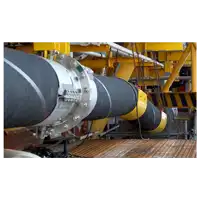 Tecalemit Flexibles strengthens its presence in the energy sector
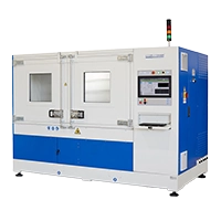 A pulse bench with exceptional capabilities
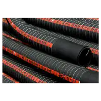 Hose type approvals for the transport of hazardous materials
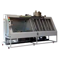 A depollution bench of our design
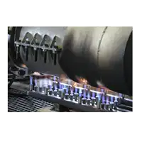 BV type certification for fire resistant hoses
 DE
DE  ES
ES  EN
EN  FR
FR