Technical guide for hydraulic hoses
Hoses selection
Hoses selection
Preface : reminder on hose structure
A hose has 3 main components :
- An inner tube, for oiltightness, is made from homogenous polymer with excellent resistance to the product conveyed.
- A reinforcement giving the hose its physical and mechanical properties : resistance to pressure, to vacuum, resistance to kinking, tensile strength.
This reinforcement can combine several technical solutions to adapt to conditions of use : textile or metal braiding or spirals, plastic or metal spirals, cable spirals, electrical conductors.
More over, it guarantees the dimensional shape of the inner tube, thereby contributing to tightness of the hose.
- The outer cover is made from homogenous polymer and destined to isolate the reinforcement from the environment.
General criteria:
The user or prescriber should take the following aspects into consideration :
environment :
- Safety of operators
- Protection of the environment
- Ambient temperature
- Atmospheric conditions
- Risk of impacts or abrasion
- Presence of corrosive products
State of product conveyed :
Liquid, gaseous, solid or a combination of same
Method of use :
By suction, pressure or assisted
Conditions of use :
Pressure and temperature of fluid, pressure surges, pressure peaks, frequency of use
Characteristics of installation :
- Imposed bend radius
- Vibrations
- Strains
- Flexions
- Acceptable fittings
The rest of this guide deals more with hydraulic hose up to inner diameter 2” (50,8mm) for oleo-hydraulic power applications and transport of gaseous fluids under high pressure.
Inner diameter of a hose:
Expressed in millimetres and fractions of an inch as well as in modules (dash-sizes). These are equal to 1/16 of an inch for all our hoses except for hose type SAE100 R5 (our hose types T510 and T511).
The inner diameter of a hose is without doubt the first criterion to choose.
Choosing a diameter too small would have for effect :
- Heating of the installation via the joule effect due to overspeeding of the hydraulic fluid flow
- Important pressure drops
- Loss of efficiency and premature wear of hydraulic pumps (suction)
Choosing a diameter too large would unnecessarily increase weight, size and cost of the installation.
Choosing the right inner diameter of hose is therefore primordial.
This table is destined to help you determine hose inner diameter. It gives pressure drops for standard oil.
| Litre/ minute | Inner diameter (mm) | ||||||||||||||||||
| 6 | 8 | 10 | 12 | 13 | 16 | 19 | 22 | 25 | 29 | 32 | 35 | 38 | 46 | 51 | 63 | 76 | 89 | 102 | |
| 1 | 146 | ||||||||||||||||||
| 2 | 291 | 92 | |||||||||||||||||
| 4 | 548 | 185 | 75 | ||||||||||||||||
| 8 | 1168 | 370 | 151 | 73 | |||||||||||||||
| 12 | 1752 | 555 | 227 | 109 | 80 | ||||||||||||||
| 16 | 2335 | 739 | 302 | 146 | 106 | ||||||||||||||
| 20 | 2927 | 924 | 378 | 182 | 133 | ||||||||||||||
| 25 | 7496 | 1157 | 473 | 228 | 166 | 72 | |||||||||||||
| 30 | 10223 | 2626 | 567 | 274 | 199 | 87 | |||||||||||||
| 40 | 16751 | 4332 | 1429 | 366 | 265 | 115 | |||||||||||||
| 50 | 24649 | 6362 | 2173 | 921 | 633 | 145 | 72 | ||||||||||||
| 60 | 8705 | 2966 | 1252 | 860 | 325 | 87 | 48 | 29 | |||||||||||
| 75 | 4346 | 1832 | 1254 | 471 | 211 | 60 | 36 | 20 | 13 | ||||||||||
| 90 | 2502 | 1711 | 643 | 286 | 143 | 79 | 24 | 16 | |||||||||||
| 100 | 2049 | 767 | 341 | 172 | 94 | 47 | 18 | 13 | 9 | ||||||||||
| 120 | 1047 | 465 | 233 | 128 | 64 | 40 | 15 | 11 | |||||||||||
| 140 | 605 | 303 | 166 | 83 | 52 | 34 | 23 | 5,9 | |||||||||||
| 160 | 760 | 380 | 208 | 104 | 65 | 43 | 29 | 12 | 4,5 | ||||||||||
| 180 | 931 | 465 | 254 | 126 | 80 | 52 | 36 | 15 | 9 | 2,2 | |||||||||
| 200 | 1117 | 557 | 304 | 151 | 95 | 62 | 42 | 17 | 11 | 2,4 | 1,1 | ||||||||
| 240 | 761 | 416 | 206 | 130 | 85 | 57 | 24 | 15 | 5,4 | 1,4 | 0,7 | ||||||||
| 280 | 268 | 168 | 110 | 75 | 31 | 19 | 7 | 2,9 | 1 | 0,5 | |||||||||
| 320 | 212 | 139 | 94 | 38 | 24 | 8,7 | 3,6 | 1,7 | 0,6 | ||||||||||
| 360 | 170 | 115 | 47 | 28 | 11 | 4,4 | 2,1 | 1,1 | |||||||||||
| 400 | 203 | 138 | 56 | 34 | 13 | 5,3 | 2,5 | 1,3 | |||||||||||
| 450 | 169 | 69 | 42 | 16 | 6,4 | 3,1 | 1,6 | ||||||||||||
| 500 | 202 | 82 | 50 | 19 | 7,7 | 3,7 | 1,9 | ||||||||||||
| 600 | 112 | 69 | 25 | 10 | 5 | 2,6 | |||||||||||||
| 700 | 146 | 90 | 3,3 | 14 | 6,5 | 3,4 | |||||||||||||
| 800 | 184 | 113 | 42 | 17 | 8,1 | 4,3 | |||||||||||||
| 900 | 227 | 139 | 51 | 21 | 10 | 5,2 | |||||||||||||
| 1000 | 167 | 61 | 25 | 12 | 6,3 | ||||||||||||||
| 1200 | 230 | 84 | 35 | 16 | 8,6 | ||||||||||||||
| Laminary flow | Transitory flow | Turbulent flow | ||||
| Table of pressure drop in millibars (mb) per metre of rubber hose without end-fittings by inner diameter in millimetres and by flow rate in litres per minute (l/m) for a standard hydraulic oil of 31,8 centistokes (mm2/s) and with a density of 878 kg/m3. | ||||||
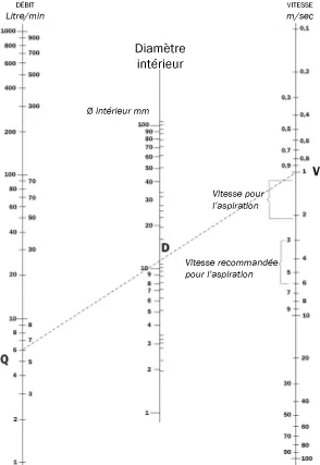
The following abacus corresponds the flow rate (in litres per minute), the inner diameter (in millimeters) and the speed (in meters per second) of a fluid within a hose.
It is just necessary to trace a straight line through two known values to obtain the third.
In the example shown by a dotted line, for a flow Q of 6 l/m, to have a speed V of 1 m/s, it is necessary to have an inner diameter d of roughly 12mm.
Part of the energy necessary for the transfer of fluid in the hose is lost through friction : it is called pressure drop.
This is proportional to the speed of the fluid at low speeds.
At higher speeds it becomes proportional to the square root of the speed and therefore excessive.
The limit between these two possibilities is identifiable by the Reynolds number which must be inferior to 2300 for the flow to be satisfactory.
Reynolds number = Re = V.D/nu <2300
V = speed of fluid in millimeters per second
D = inner diameter of hose in millimeters
nu = kinematic viscosity in centistokes
when the Reynolds number is lower than 2300, it is said to be laminary, when it is between 2300 and 3000 it is called transitory and for values above, it is said to be turbulent.
Working pressure:
Expressed in bar with the abbreviation WP.
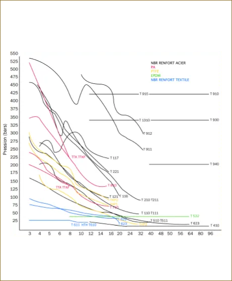
Tecalemit flexibles hoses are designed and produced to work continuously at the working pressures indicated on each data sheet and repeated in the table by diameter and type.
As an idincation, it is considered that using a hose at 20% higher pressure than recommended reduces life span by half.
Table of tecalemit flexibles® hose:
| Working pressure (in bars) | |||||||||||||||||||
| Hose | module | ||||||||||||||||||
| 3 | 4 | 5 | 6 | 8 | 10 | 12 | 14 | 16 | 20 | 24 | 32 | 40 | 48 | 50 | 56 | 64 | 80 | 96 | |
| TTA | 245 | 225 | 180 | 160 | 140 | ||||||||||||||
| TTAF | 245 | 225 | 180 | 160 | 140 | ||||||||||||||
| TTK | 530 | 450 | 370 | 300 | 230 | ||||||||||||||
| TTKF | 530 | 450 | 370 | 300 | 230 | ||||||||||||||
| T710 | 207 | 190 | 172 | 155 | 138 | 103 | 86 | 69 | |||||||||||
| T810 | 345 | 345 | 310 | 275 | 240 | 190 | 155 | 138 | |||||||||||
| T110 | 287 | 242 | 237 | 203 | 171 | 142 | 123 | 91 | 68 | 61 | 49 | ||||||||
| T111 | 287 | 242 | 237 | 203 | 171 | 142 | 123 | 91 | 68 | 61 | 49 | ||||||||
| T116 | 350 | 453 | 412 | 282 | 338 | 262 | 225 | 157 | 100 | ||||||||||
| T117 | 263 | 275 | 236 | 286 | 296 | 243 | 214 | ||||||||||||
| T121 | 261 | 236 | 212 | 183 | 169 | 111 | 95 | ||||||||||||
| T210 | 463 | 453 | 379 | 365 | 304 | 270 | 219 | 173 | 133 | 96 | 88 | ||||||||
| T211 | 463 | 453 | 379 | 365 | 304 | 270 | 219 | 173 | 133 | 96 | 88 | ||||||||
| T221 | 450 | 384 | 357 | 310 | 276 | 236 | 181 | ||||||||||||
| T261 | 400 | 400 | |||||||||||||||||
| T331 | 103 | 86 | 83 | 78 | 69 | 60 | 52 | 39 | 26 | ||||||||||
| T410 | 21 | 17 | 14 | 10 | 10 | 10 | 10 | 10 | 10 | ||||||||||
| T462 | 25 | 25 | 25 | 25 | 25 | 25 | 25 | ||||||||||||
| T510 | 207 | 207 | 155 | 138 | 121 | 103 | 55 | 43 | 34 | 24 | 24 | ||||||||
| T610 | 28 | 28 | 28 | 28 | 24 | 22 | |||||||||||||
| THTH | 28 | 28 | 28 | 28 | 24 | 22 | |||||||||||||
| T611 | 34 | 28 | 28 | 28 | 28 | 24 | 22 | ||||||||||||
| T622 | 80 | 75 | 68 | 63 | 58 | 50 | 45 | 40 | 35 | ||||||||||
| T623 | 160 | 145 | 130 | 110 | 93 | 80 | 70 | 55 | 45 | 40 | 33 | 25 | 18 | 18 | |||||
| T911 | 540 | 501 | 448 | 384 | 456 | 357 | 305 | 279 | 252 | ||||||||||
| T912 | 521 | 456 | 452 | 365 | 361 | 295 | |||||||||||||
| T915 | 420 | 420 | 420 | 420 | 420 | ||||||||||||||
| T920 | 210 | 210 | 210 | 210 | 210 | ||||||||||||||
| T930 | 345 | 345 | 345 | 345 | 345 | ||||||||||||||
| T940 | 420 | 420 | 420 | 420 | 420 | ||||||||||||||
| T961 | 1000 | 850 | 800 | 750 | 700 | ||||||||||||||
| T962 | 1250 | 1100 | 1000 | ||||||||||||||||
| T1310 | 345 | 345 | 345 | 345 | 345 | ||||||||||||||
| T1362 | 1400 | 1200 | 1000 | 900 | |||||||||||||||
| VKI | 190 | 172 | 155 | 138 | 103 | 86 | 69 | ||||||||||||
| VI | 110 | 100 | 90 | 97 | 85 | 78 | 65 | ||||||||||||
| T532 | 43 | 43 | 43 | 43 | 43 | 43 | 43 | 43 | 43 | 43 | |||||||||
| TH P1 | 276 | 224 | 207 | 183 | 161 | 115 | 103 | 92 | 80 | ||||||||||
| TH P2 | 310 | 253 | 237 | 206 | 189 | 133 | 126 | 115 | 93 | ||||||||||
| TH P3 | 172 | 133 | 138 | 103 | 83 | 69 | 57 | 46 | 34 | 30 | 23 | ||||||||
| GA | |||||||||||||||||||
| GC | |||||||||||||||||||
Graphical chart of working pressures according to hose:
Test pressure:
Expressed in bar with the abbreviationTP.
Test pressure is generally twice the working pressure, it should be maintained for over 30 seconds without exceeding 15 minutes.
Overpressure, pressure surges:
Hydraulic circuits generally present pressure surges and/or temporary overpressures whose values exceed the nominal admissible pressures for the majority of the circuits components.
In this case, it is necessary to increase the safety factor, which is usually 4, between the working pressure and the theoretical burst pressure.
Tthis safety factor can be reduced to 3.15 if no pressure surges are present.
Burst pressure:
Expressed in bar with the abbreviation of BP.
The values indicated on Tecalemit Flexibles® data sheets are before bursting.
They are guaranteed for hoses having never been in use and equipped with fittings in the preceeding month.
Working temperatures:
The temperatures specified in Tecalemit Flexibles® data sheets are the maximum admissible working temperatures for the hose with standard hydraulic oil.
It can be considered that 10°C higher in temperature can halve the life span.
For other fluids, please contact our technical department, as the maximum admissible temperature could be higher or lower than indicated.
iIt is strongly advised not to use hoses at maximum pressures and temperatures at the same time.
Hose assemblies can be used in different ambient temperatures after having been protected by an adequate heat-resistant sheath, without which the outer cover would be subjected to premature aging, harden and become brittle.
Bend radius:
Expressed in millimeters, bend radii are indicated by measuring from the centreline of the hose, at maximum working pressure and without flexing of the hose.
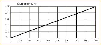
Should there be flexing of the hose, minimum bend radius should be increased by the multiplication factor N in the table below.
A lower bend radius can be acceptable, provided the working pressure is lowered.
Tensile strength:
Any pulling forces must be made in the centreline of end-fittings.
Only hoses with metal reinforcement can sufficiently resist off-centreline pulling forces.
Pulling forces should be avoided on suction hoses incorporating a wire spiral as well as hoses intended to transmit power via hydraulic oil.
They would have for effect to reduce admissible working pressure and the internal dimension of the hose.
Vacuum resistance:
All our suction hoses have maximum vacuum resistance.
Also, our data sheets indicate maximum admissible vacuum values for high pressure hoses with metal reinforcement, as well as the SAE 100 R3 hose with textile reinforcement.
Accidental kinking or flattening are particularly detrimental to vacuum resistance of hoses.
Vibrations:
Tecalemit Flexibles® hoses are manufactured to withstand vibrations.
In order to optimise their life span, it is recommended to avoid them in as much as possible, as vibrations (and flexions) are the main sources of wear and heating, particularly at end-fittings.
Twisting:
Twisting must be avoided. They give way to a rapid deterioration of hoses.
Chemical resistance:
Compatibility of the hose inner tube with the fluid conveyed must be ascertained.
In the same respect, the outer cover and its environment should be taken into consideration.
The table of chemical resistance found in this catalogue gives the main information, but please contact our technical department in case of doubt.
Gaseous fluids:
Hoses must be adapted to conveying gaseous fluids when necessary.
The hose outer cover must be micro-perforated, in order to eliminate any gas build-up in the hose reinforcement structure.
Other precautions should be taken in assembling and installing the hose. these are detailed in the technical handbook.
Metal spiral hose cannot convey gaseous fluids (microperforation is not possible).
Electrical conductivity:
In general, it can be said that metal-reinforced hoses are conductive and that textile-reinforced hoses are not.
Resistance per metre of hose inner tube and outer cover should be taken into consideration, and also that between the inner tube and the cover.
For special application, please consult the technical department.
Dimensional stability:
Tecalemit Flexibles® high pressure hose is manufactured with a braid angle which geometrically cancels any dimensional modifications due to pressure, that is : stretching with reduction of diameter or, alternatively, retraction accompanied by an increase in diameter.
Even so, it strongly advised to check measurements during pressure tests.
Use & maintenance
Use & maintenance
During use, a hose can be subjected to many effects for which it has not been foreseen.
Obviously, it is recommended to use a hose according to data sheets concerning working pressure, temperature, bend radius... Please contact us in case of doubt on the combination of the different factors.
Protection in service:
Accessories destined to protect hoses can be found at the end of this catalogue. The GA sheath is made from braided fibre glass with silicon induction, available in various thicknesses and a large range of diameters for heat protection of hose. The GC sheath is in SBR/EPDM on a textile support affording mechanical and ultraviolet protection.
Manipulation:
Hoses should be handled with precaution, must not be dragged over abrasive or sharp surfaces, avoid knotting, trampling or flattening under vehicles.
Products conveyed:
Please consult us should the hose be used for a product different than the one foreseen.
A chemical compatibility chart for hose inner tubes can be found this website.
Torsion:
Should the relative movement result in a torsion of the hose, end connections should be modified to give way to a flexion of the hose rather than torsion.
Tensile strength:
Please consult us with details of any pulling forces that our hoses could be subjected to.
Protection of operators:
High pressure hoses, when used in the presence of operators, should be equipped with our patented protecalan® sheathing, combining anti-whip cables and spray-guard.
The combination of these two devices ensures the total protection of operators in conformity with NF EN ISO 4413 which defines the general rules relative to hydraulic installations.
Once per year, it is recommended that hoses be visually inspected after cleaning.
The following defects should impose the replacement of the hose :
- leaks or traces thereof
- ripped or torn outer cover
- slipping of end-fitting
- abrasion or notches leaving reinforcement exposed
Storage
Storage conditions
Over long periods, particularly when exposed to certain factors described herebelow, hoses can be modified in such a way as to no longer have their initial physical properties.
Storage time:
The right storage conditions can give maximum protection and reduce deterioration of the polymers.
Bulk hose :
Indicated life spans are valid only if hose is stored in the conditions described in the following paragraphs.
Elastomer hose :
- Up to 3 years old : can be used without restrictions
- Between 3 and 6 years : visual inspection, test samples at 2 times working pressure
- 6 to 8 years : full visual inspection, carry out destructive and impulse tests on samples
- Over 8 years : do not use
Thermoplastic hose :
- For polyurethane cover hoses (sae100r7 and R8, tecalemit hoses ttaf and ttkf) please refer to elastomer hose recommendations above.
- Tecalemit Flexibles® hoses tta and ttk, life span is twice as long in normal use. it can be longer in certain cases : please contact our technical department (bs iso 2230:2002)
Hose assemblies installed on equipment :
Hoses containing the usual liquid and installed on equipment unused for over 3 years should be tested at twice the working pressure and should be replaced if over 5 years.
In every case, a careful visual inspection should be made, particularly where hose bends and at connections between hose and swage ferrule.
All Tecalemit Flexibles® hoses carry a number used to identifiy date of manufacture and the date at which hose was placed in stock.
Temperature:
The ideal storage temperature is 15°C and the acceptable range is between 0°C and 35°C.
Hoses should therefore not be placed near a source of heat.
In any case, stored hoses should not be subjected to temperatures in excess of 50°C or lower than - 30°C.
Moreover, any important fluctuations of temperature during storage could lead to premature aging of the hose.
Any cracking of the outer cover due to ozone effects increase with temperature.
Humidity:
It is recommended to avoid humidity in excess of 65%.
Ultraviolet rays:
Direct light is a major source of aging. items should not be subjected to sunlight or strong artificial light.
Should the storage area have windows, these should be covered with protective red, orange or white film, or use opaque packing on the items.
Ozone:
Ozone is a factor of aging that must be taken into account.
Storage areas should not contain any ozone generators such as mercury lamps or electrical equipment producing sparks such as AC electrical motors.
Moreover, circulation of air around and inside the hoses should be limited, for instance by leaving the original packing on the hose and plugging the hose ends.
Environment:
Storage areas should be separated from workshops where the items could be subjected to projections of oil, solvants, detergents.
Storage bend radius:
Ozone is major factor of aging which, in particular, causes cracking in the ruber outer cover.
When the hose is bent, the strain on the outer cover has a tendency to increase the cracks.
Consequently, the smaller the bend radius, more likely the risk of cracks appearing.
Storage method:
Ideally, hoses should be stored by laying them straight on a flat support with ends plugged.
Should hoses have to be stored in rolls, these should not be piled one on top of the other, and in no case should there be any permanent flattening of the sructure due to piling.
Hoses should not be hung on hooks and generally should not be subjected to any flexion or traction.
Chemical compatibility

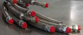

 Department specialized in manufacturing high-quality industrial hoses for fluid transfer.
 Specialist in the manufacturing of hydraulic hoses, extrusion of pneumatic tubes, and production of thermoplastic preforms.
 Wide selection of industrial and hydraulic hoses and fittings in the Paris region.
 Machining of fittings for industrial and hydraulic hoses, crimped ferrules, and stainless steel corrugated hoses.





 Type approval certificates for hydraulic hoses
 Development of the company and its infrastructures
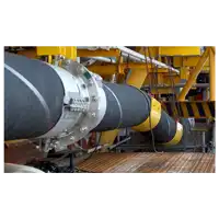 Tecalemit Flexibles strengthens its presence in the energy sector
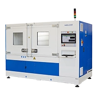 A pulse bench with exceptional capabilities
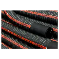 Hose type approvals for the transport of hazardous materials
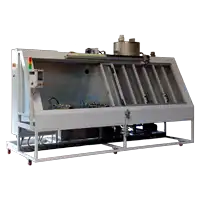 A depollution bench of our design
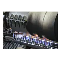 BV type certification for fire resistant hoses
 DE
DE  ES
ES  EN
EN  FR
FR